-
-
ApplicationOur products consist of undercarriage parts for bulldozer and excavator such as Track link,Track roller,Carrier roller,Sprocket,ldler,Track shoe,Cutting edge,End bit,Tooth Bucket,Track pin,Track bush, Engine parts,Track boit&nuts.U-bolt,Centre bolt,Wheel bolt and other related parts.

-
About UsFujian Yongsheng Machinery Parts Co., Ltd. is located in Quanzhou City, Fujian Province, which is one of the most developed regions of China Machinery Manufacturing.The company was established in 2003, after approximately 10years' effort, and now it is one of the leading construction machinery parts auto parts manufacturers in CHINA.
-
BlogSuppliers who pass Quality ManagementSystem Certification, and have onsitematerials or finished products inspected,as certified by independent third parties.
Heavy Equipment Undercarriage Wear Guide: Component Diagnosis & Replacement Indicators
Comprehensive heavy equipment undercarriage wear guide. Learn how to diagnose track roller flat spots, track chain elongation, sprocket wear, and determine optimal replacement timing.
Jul 08,2026
Heavy Equipment Undercarriage Wear Guide: Component Diagnosis & Replacement Indicators
The crawler undercarriage is a heavy machinery investment that commands careful operational tracking. Accounting for roughly half of all maintenance expenditures throughout a machine's service cycle, tracking wear patterns on tracked excavators and bulldozers is paramount. Unplanned undercarriage degradation results in severe project delays and compounding mechanical strain. This comprehensive heavy equipment undercarriage wear guide provides technical insights into component failures, wear limit thresholds, and strategic replacement scheduling.
The Mechanics of Track Wear: Interdependent Systems
Unlike isolated machine components, an undercarriage works as an unbroken mechanical chain. If a singular part goes out of specification, it accelerates wear across every adjacent component. For instance, when a track link stretches, it shifts the landing position of every subsequent link onto the drive sprocket teeth, wearing down both parts simultaneously. Fleet managers must understand the warning signs for each underlying component to intercept failure early.
1. Track Rollers & Carrier Rollers Wear Metrics
Track rollers (bottom rollers) bear the direct working load of the equipment, while carrier rollers (top rollers) sustain the upper track loop tension. Both components handle heavy structural forces mixed with abrasive dirt, mud, and rocks.
Excavator Track Roller Wear Limits & Symptoms
Rollers typically display wear on their outer tread diameters and guiding flanges. Once induction-hardened boundaries wear down past acceptable parameters, the roller shell thinness compromises its structural payload capability.
- Flange Wear: Side thrusting from constant working on slopes causes track link rails to cut into roller flanges. When flange reduction reaches 30% to 40%, track alignment stability drops significantly.
- Carrier Roller Flat Spots Troubleshooting: If clay or frozen mud jams a top roller, the track link slides over a stationary shell. This creates distinct flat spots on the tread. Once jammed, a carrier roller cannot be salvaged and requires direct replacement.
| Undercarriage Component | Primary Wear Pattern | Max Allowable Wear Limit | Operational Diagnostic Sign | Consequence of Neglect |
|---|---|---|---|---|
| Track Rollers (Bottom) | Tread Diameter Reduction / Flange Wear | 30% - 35% Material Loss | Machine leans slightly; guiding rails scrape frame | Link rail destruction; roller shell cracking |
| Carrier Rollers (Top) | Tread Flat Spots / Seizure | 25% Tread Material Loss | Visible frozen roller; tracking slapping noises | Accelerated track link rail wear and vibration |
2. Track Link Assembly & Chain Wear Diagnosis
The track link assembly forms the foundational track line. Whether utilizing sealed-and-greased structures for excavators or Sealed and Lubricated Tracks (SALT) configurations for heavy bulldozers, track chains undergo heavy dimensional transformations.
Track Link Elongation Pitch Measurement
True "track stretch" is rarely a bending of solid steel links; instead, it is driven by internal wear between internal pins and matching bushings. As the contact spacing thins out, the total distance between link pins expands. This phenomenon is evaluated through a track link elongation pitch measurement across four consecutive link segments.
Technical Guide: Measuring Track Link Pitch Stretch
Using a precision caliper, measure the distance from the leading edge of one pin to the leading edge of the fifth pin over a stretched section of track. If the resulting measurement exceeds factory specifications by more than 4% to 5%, internal pin-and-bushing lifecycles are maxed out, requiring immediate field intervention.
3. Sprockets & Sprocket Segments Replacement Identifiers
Sprockets channel high drive torque directly into the moving track chain loop. Because they encounter constant abrasive friction, keeping tabs on drive teeth profiles helps save track pins from early failure.
When to Replace Excavator Sprocket Segments
Healthy drive teeth have rounded, sturdy profiles that distribute driving forces symmetrically. As wear advances, the profiles shift shapes noticeably.
- Knife-Edge Profiles: Abrasive soils reduce the tops of sprocket teeth into sharp, narrow edges. Operating with knife-edge profiles ruins track bushing diameters within a matter of weeks.
- Root Pocket Gouging: When track links stretch out of pitch, the bushings land incorrectly into the root pocket of the sprocket teeth. This creates localized gouges that quickly hook the link assembly.
Sprocket segments must always be replaced when installing new track link assemblies. Running a new track chain on worn sprockets completely destroys the new component investment within a fraction of its expected lifecycle.
4. Front Idlers & Track Shoes Performance Wear
Front idlers maintain track loop centration and operate alongside heavy spring or hydraulic recoil tension systems to dissipate severe impact energy. Track shoes handle raw contact with external working soils.
| Component Group | Key Failure Symptoms | Root Cause Identification | Best Practice Action |
|---|---|---|---|
| Front Idler Assembly | Center tread wear, side guide plate thinning, seal leakage | Continuous directional tracking; side-loading stress | Rebuild via welding overlay if within wear limits; replace if cracked |
| Track Shoes / Pads | Grouser bar height reduction, bolt loosening, cracking | High-impact rocky operations, over-tightened track tension | Replace individual damaged pads; perform structural grouser re-welding |
Balancing Decisions: Track Link Repair vs. Replacement Criteria
A central question for fleet asset managers centers on defining the clear track link repair vs replacement criteria to maximize service life without sacrificing field safety.
Undercarriage Pin and Bushing Turning Guide
When executing a track chain wear patterns diagnosis, you may find that the internal pins and bushings are worn near their service limit on the driving side, while the reverse side remains untouched. Instead of replacing the entire track chain, a qualified shop can press out the pins and bushings, turn them 180 degrees, and press them back in.
This maintenance extension doubles the operating life of the track group for a moderate labor investment, entirely avoiding the extreme cost of a whole new link assembly.
Sourcing Strategy: OEM vs. Aftermarket Undercarriage Lifecycle
Procurement teams regularly evaluate the cost-performance balance of original equipment manufacturer (OEM) track assemblies against certified aftermarket alternatives. High-quality aftermarket suppliers utilize identical induction-hardening depths (52-58 HRC surface boundaries) and premium boron-alloyed steel compounds to match OEM field performance at a far lower capital tier. Sourcing from certified manufacturers lowers a fleet's direct hourly operating costs while maintaining total machine reliability.
Excavator Undercarriage Inspection Checklist
Implementing a strict field inspection framework helps heavy equipment operations identify early wear signatures before they trigger catastrophic part failures:
- Every 10 Operating Hours (Daily): Visually inspect for clear mirror seal oil leaks on track rollers and front idlers. Clean out packed rocks or hard clay from the roller frames.
- Every 50 Operating Hours (Weekly): Complete an accurate track sag tension test. Adjust the hydraulic grease valve to maintain specified slack and avoid tight tracking friction.
- Every 250 Operating Hours (Monthly): Perform a comprehensive heavy duty track shoe wear analysis. Check for cracked pad sections or missing shoe bolts, and measure grouser bar height metrics.
- Every 1000 Operating Hours (Bi-Annually): Execute a technical track link elongation pitch measurement. Map sprocket pocket gouging parameters to schedule upcoming maintenance windows.
Conclusion: Strategic Fleet Longevity
Managing crawler equipment undercarriages requires transitioning from reactive emergency maintenance to predictive wear control. By monitoring link stretch metrics, replacing sprocket segments systematically, and utilizing pin-and-bushing turning frameworks, procurement and fleet managers can unlock the full wear life of their chassis investments, securing reliable uptime across every project site.
Connect with Our Engineering Support Team
For detailed technical specifications, volume aftermarket component quotations, or custom multi-brand cross-compatibility inquiries:
Corporate Email: sales@china-ysm.com
Technical Hotline / WhatsApp: +86 18016757808
We supply precision-forged track components engineered to lower your fleet's long-term cost-per-hour.
Related Posts
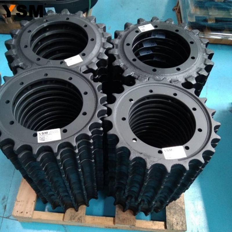
How Should The Supporting Wheels Be Selected To Avoid Stepping On Thunder?
High-quality support wheels mainly depend on the performance of its steel. The material of the roller body is generally 50Mn, 40Mn2, (MN: synonymous with the element of manganese).
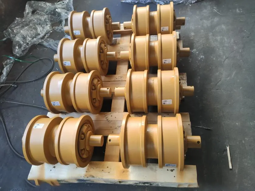
Carrier Wheels Are Suitable For Various Models At Home And Abroad
Sprocket wheels are mainly used in various crawler bulldozers, excavators, pavers, milling machines, rotary drilling rigs or other crawler machinery equipment at home and abroad.
Contact Us
E-mail :
sales@china-ysm.com
Phone/WhatsApp:
+86-18606961587
Address:
No.8 Binjiang Street, Binjiang Industrial Zone, Xiamei Town, Nan An City, Quanzhou City, Fujian Province, China
Request Quote
Andy Shi
No.8 Binjiang Street, Binjiang Industrial Zone, Xiamei Town, Nan An City, Quanzhou City, Fujian Province, China


Request Quote