
Excavator parts fitment guide | Updated August 7, 2026
How to Measure an Excavator Track Roller Before Ordering
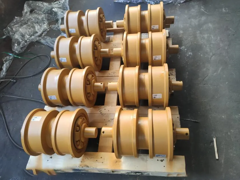
An excavator track roller can look correct in a photograph and still fail to fit the track frame, mounting holes or chain geometry. The safest ordering method starts with the machine identity and part number, then uses a consistent set of roller and mounting dimensions as confirmation. This guide explains which measurements matter, where common mistakes occur and what to send to a supplier before a replacement is approved.
Quick answer
Record the machine brand, complete model and suffix, serial number/PIN and old roller part number first. Then confirm whether the part is a lower track roller or upper carrier roller, its position, flange design, track type, mounting style, mounting width, longitudinal and transverse bolt spacing, hole or thread specification, tread diameter, flange diameter, shaft dimensions and relevant inside/outside spread. Photograph every measurement. Do not treat dimensions from a worn roller as new-part specifications without checking a drawing or parts catalog.
Why the excavator model alone may not identify the roller
A model family can include different serial ranges, track gauges, undercarriage options and steel-track or rubber-track configurations. The number and arrangement of single-flange and double-flange rollers may also change by design. A supplier therefore needs more than a short model name such as a familiar three-digit excavator designation.
Current Caterpillar parts data illustrates the number of variables involved: an individual track roller specification may list flange type, tread diameter, mounting width, link outside spread, inside spread, mounting-bolt spacing, hole or thread size, shaft length and shaft outside diameter. Linser likewise identifies reference number, full model, undercarriage version, roller position, flange design, track type and dimensions as decisive selection points.
Confirm that you are measuring the correct component
| Term | Position and function | Common ordering risk |
|---|---|---|
| Track roller / bottom roller / lower roller | Works along the lower track run to support machine weight and guide the chain. | Confused with a carrier roller or supplied with the wrong flange position. |
| Carrier roller / top roller / upper roller | Supports the upper return run of the track. | Called a track roller in general conversation even though its mounting and geometry differ. |
| Single-flange roller | Has one principal guide flange in the design. | Assumed to be interchangeable with a double-flange position. |
| Double-flange roller | Uses guide geometry on both sides of the running path. | Installed in an unintended position or compared only by body diameter. |
| Complete roller assembly | Product-specific assembly that may include the roller body, shaft, seals and mounting ends. | Quotation scope is unclear; a body or subassembly is mistaken for a ready-to-install part. |
Flange count is not a quality grade. It is part of the undercarriage layout. Record the old roller's exact position from the front idler toward the rear sprocket before removal, and photograph the neighboring rollers so the intended arrangement remains clear.
Prepare the machine and roller safely
Park the excavator on firm, level ground, lower the attachment, isolate the machine and follow the exact operation and maintenance manual. A track roller sits beneath a very heavy structure and may remain loaded even when the machine appears stationary. Do not loosen roller fasteners, split the track, lift the machine or work beneath it without the specified support method, rated equipment and qualified personnel.
For a removed roller, clean soil and loose scale from the mounting faces and measurement points. Do not grind a surface merely to make it easier to measure; that changes the evidence. Mark the machine side, roller position and installation direction before moving the part to a bench.
Useful tools and recording method
- steel tape for larger overall dimensions;
- caliper of suitable range for holes, shafts, flange thickness and smaller distances;
- straightedge or square to establish repeatable reference planes;
- thread-pitch gauge and known fastener, used only by a competent technician;
- paint marker and position tag;
- camera or phone for a straight-on photograph of every reading;
- manufacturer drawing, parts catalog or wear chart when available.
Use millimeters unless the supplier requests another unit. Write the unit beside every value. A photograph of a tape without a written dimension is easy to misread because of angle and parallax. For critical spacing, take at least two readings and identify whether the value is center-to-center, edge-to-edge or overall.
Track roller dimensions to record
| Measurement | How to describe it | Why it matters |
|---|---|---|
| Mounting width | Width across the specified mounting faces or support area; show the chosen endpoints in a photo. | Must suit the track-frame mounting arrangement. |
| Longitudinal bolt spacing | Center-to-center distance between holes along the machine's travel direction. | Controls alignment with the frame holes or caps. |
| Transverse bolt spacing | Center-to-center distance across the roller or frame where applicable. | Distinguishes similar-looking mounting patterns. |
| Hole diameter or thread | Hole diameter, fastener diameter and thread pitch/type if the mounting is threaded. | Prevents a roller from fitting the spacing but rejecting the correct fastener. |
| Tread diameter | Diameter of the chain-contact running surface at the drawing's specified point. | Affects machine height, load sharing and contact with the link rail. |
| Outer flange diameter | Largest diameter of the guide flange. | Helps verify flange geometry and track clearance. |
| Inside and outside spread | Distances between the specified tread or flange reference faces. | Relates the roller to link spread and lateral guidance. |
| Shaft length and shaft OD | Overall or exposed shaft length and outside diameter at the drawing's datum. | Confirms mounting construction and bearing/shaft envelope. |
| Overall height or mounting-to-tread height | Distance from the clean mounting datum to the running surface. | Helps identify a roller that would change rail contact or fail to sit correctly. |
| Flange arrangement | Single, double, inner, outer or other design, plus the intended position. | Must match chain guidance and the roller sequence. |
Dimension names vary among drawings and suppliers. Never send a letter such as A, B or C without including the corresponding marked photograph or drawing; different catalogs may assign the same letter to different features.
Step-by-step measurement workflow
- Photograph the machine plate. Capture the brand, complete model, suffix and serial number/PIN clearly.
- Photograph the roller in position. Include the entire undercarriage side and a closer view showing its sequence from the idler.
- Record the part number. Clean the marking gently and photograph it before removal. Do not guess unclear characters.
- Identify track and flange design. State steel or rubber track, lower or upper roller, single or double flange and installation position.
- Measure the mounting pattern. Record longitudinal and transverse center spacing, hole count, hole diameter and thread/fastener details.
- Measure mounting and shaft dimensions. Show the exact faces used for width, height, shaft length and shaft diameter.
- Measure tread and flange geometry. Record tread diameter, flange diameter and the relevant inside/outside spread at repeatable points.
- Cross-check the frame. When safe and accessible, compare the frame mounting faces and hole pattern with the removed part.
- Record wear and damage. Note reduced tread diameter, sharp flanges, bent ears, elongated holes, leakage or previous repair.
- Send one organized data set. Label photographs and dimensions so the supplier does not combine values from different rollers or machines.
Why a worn roller can give misleading dimensions
The running surface and flanges are wear areas. Their present diameters may be smaller than the new specification, and one side may be worn more heavily. Bent mounting ears, elongated holes, corrosion or impact damage can also change measurements. Take several readings around the circumference and record the largest and smallest result instead of selecting one convenient point.
Mounting faces and bolt centers are generally more useful for fitment than a heavily worn tread, but even mounting features can be damaged. Compare the old component with the track frame and a verified drawing. If a new roller has to share load with several worn rollers, the difference in effective height and the condition of the chain rails should be assessed before installation.
Measure the roller and the machine-side interface
A replacement part must match two interfaces: the track frame above and the track chain below. Measuring only the loose roller can miss a modified bracket, worn saddle or repaired frame. Measuring only the frame can miss the required flange and tread geometry.
Inspect the mounting seat for burrs, deformation, cracked welds, packed material and damaged threads. Check whether the roller uses through-bolts, caps, threaded ends or another machine-specific arrangement. Do not assume that a similar bolt count means the same pattern. The center spacing, thread, seating shape and mounting height must work together.
Below the roller, examine chain rail width and contact pattern. Bright contact on a flange, one-sided rail wear or repeated roller damage may indicate track tension, alignment, operating pattern, idler position or frame issues. A new roller cannot correct these causes by itself.
Common ordering mistakes
- Sending only a short excavator model without suffix or serial number.
- Calling an upper carrier roller a lower track roller.
- Ignoring the roller's position and single/double-flange sequence.
- Measuring from hole edge to hole edge but describing the result as center-to-center.
- Mixing millimeters and inches or omitting units.
- Using a perspective photograph that hides the measurement endpoints.
- Copying dimensions from another online listing because the part looks similar.
- Treating a worn tread or bent mounting ear as an original dimension.
- Ordering one roller without checking chain rails, neighboring rollers, idler, sprocket and alignment.
- Assuming steel-track and rubber-track rollers are interchangeable.
Inspect the complete undercarriage before installation
A track roller supports the chain and guides the lower run, so its wear pattern reflects the system around it. Check neighboring rollers for leakage, seizure and height differences. Inspect link rails for uneven contact, shoe hardware for looseness, the idler and sprocket for alignment, and the track adjuster for correct function.
Track tension must be measured using the exact machine manual and specified machine position. There is no universal sag dimension. If the track is packed with material, clean it before measurement. Excessively tight or loose conditions can influence roller and flange wear and may obscure the original cause of failure.
Installation torque, fastener reuse, thread preparation and lifting procedure are model-specific. Use the service information for the exact serial range. After installation, perform the required checks at low risk and inspect for abnormal contact, heat, noise or leakage before returning the machine to full work.
Track roller quotation checklist
- machine brand, complete model and suffix;
- serial number or PIN and nameplate photograph;
- part number and all visible markings;
- lower track roller or upper carrier roller;
- left/right side and roller position counted from the front idler;
- steel-track or rubber-track undercarriage;
- flange design and mounting type;
- marked photographs of all requested dimensions;
- clear views of mounting faces, holes, shaft ends, tread and flanges;
- quantity, working condition and destination country.
If the part number and dimensions disagree, stop and resolve the conflict. Possible reasons include an incorrect reading, a superseded part, a changed undercarriage configuration, a repaired frame or a roller from another machine.
Frequently asked questions
Can I order an excavator track roller by model only?
Sometimes a complete model and serial range leads to one catalog choice, but do not assume this. Confirm the part number, undercarriage version, roller position, flange design and relevant dimensions.
Which dimension is the most important?
No single dimension proves fitment. The mounting pattern and interface must match, while tread, flange, shaft and track-guidance geometry must also suit the chain and roller position.
Should I measure a roller while it is still installed?
Record identification, position and accessible dimensions in place, but do not reach into loaded areas. Some critical faces require qualified removal and a safe bench inspection.
Can a single-flange roller replace a double-flange roller?
Only when the exact parts documentation specifies that configuration. Flange design and position are part of track guidance and are not interchangeable by appearance.
Are old-roller measurements enough to manufacture a replacement?
They are useful confirmation data but do not define internal design, material, heat treatment, seal construction or original tolerances. Use verified product data and technical review.
Technical references
- Caterpillar Parts: 524-6302 Track Roller Group - example of current roller terminology, flange type and dimensional specification fields.
- Linser: Track Rollers for Excavators and Crawler Undercarriages - identification by reference, model, undercarriage version, position, flange design and dimensions.
- Berco: Track Rollers for Excavators and Dozers - current roller categories and construction context.
- Undercarriage Parts Reference - measurement terminology and roller-to-frame comparison context.
The parts catalog, technical drawing, wear chart and service manual for the exact machine and serial range take priority over this general guide.
Check Excavator Track Roller Fitment
For excavator track rollers, carrier rollers and related undercarriage parts, send the machine brand, complete model and suffix, serial number/PIN, part number, roller position, flange design, clear photographs, requested dimensions, quantity, working condition and destination country.
Corporate Email: sales@china-ysm.com
WhatsApp: +86-18606961587
Final fitment, availability, pricing, delivery, warranty and supply scope require case-by-case confirmation. No universal interchangeability is implied.