
Model guide | Crawler excavator undercarriage
Komatsu PC210LC-11 Undercarriage Inspection and Parts Guide
A productive PC210LC-11 depends on more than engine and hydraulic performance. Its track chains, rollers, carrier rollers, front idlers, sprockets and shoes work as one wear system. A repeatable inspection routine helps a fleet detect developing problems, compare left-to-right wear and collect the information needed for a reliable parts inquiry.
Identify the Exact PC210LC-11 Configuration Before Inspection
The machine name is a starting point, not a complete parts specification. Komatsu literature covers PC210LC-11 and intelligent-machine-control PC210LCi-11 configurations, and regional or production differences may affect installed equipment. Older PC210 variants, different suffixes and machines with modified track groups should not be treated as automatically interchangeable.
Record the complete model from the plate, the serial number or product identification information, operating hours and the undercarriage options actually installed. Photograph the whole left and right track groups before cleaning. Then photograph any guard arrangement, shoe style, master connection, visible casting marks and readable part numbers.
Komatsu brochures describe features and available arrangements such as track roller guards and triple-grouser shoes. A brochure option is not proof that the same arrangement is fitted to every machine. Physical inspection and serial-specific documentation take priority.
This model is used here as a current search-active candidate because official product literature and current aftermarket parts pages remain visible in search results. That is evidence of continuing information demand, not a verified sales ranking or a claim about monthly keyword volume.
Daily PC210LC-11 Undercarriage Walk-Around
A short inspection at the start and end of a shift can reveal a fresh leak or impact mark before it becomes a larger repair. Consistency matters: use the same route around the machine and record which side is being inspected.
- Look from a safe distance. Check whether one side sits differently, a shoe is displaced, the track appears unusually tight or loose, or packed material is lifting the chain.
- Check for leaks. Look around track rollers, carrier rollers, the front-idler area and final-drive area. Dirt stuck to a fresh oil film can be an early clue.
- Inspect hardware. Note missing, loose or damaged shoe bolts and any shiny movement marks around bolt heads or shoe seats.
- Remove harmful packing. Clean mud, frozen material, wire and stones using an approved method. Do not put hands into a loaded pinch point.
- Listen during controlled travel. Clicking, knocking, squealing or a repeated rhythm can help locate a problem, but sound alone does not diagnose the component.
- Compare both sides. One-sided wear often reflects operating direction, slope work, turning patterns, packing or alignment conditions.
Photographs should include a wide view for context and close views for detail. Add the date, machine hours, work area and side of the machine. This turns a casual walk-around into a usable maintenance history.
Track Chain, Pins and Bushings
The track chain carries the machine and transfers drive force between the sprocket and shoes. Pin-and-bushing joints articulate around the idler, rollers and sprocket. Wear changes pitch and affects how the chain engages the sprocket, so chain and sprocket condition must be evaluated together.
What to inspect
- cracked, damaged or deformed links;
- dry, leaking or abnormal joints;
- external bushing wear and uneven contact patterns;
- pin movement, abnormal end play or shifted joints;
- rail-height and link-surface wear at the specified reference points;
- shoe movement or damaged mounting surfaces.
A dry-looking joint, hot joint or local squeak deserves attention, but contamination may hide the source. Clean and compare adjacent joints. Thermal tools can support an inspection when used correctly, yet a temperature difference is a screening clue rather than a stand-alone repair decision.
Do not estimate remaining life from one photograph or one link. Measurements should be taken at the correct positions and compared with the wear chart for the installed chain. A mixed pattern may require more samples than a uniform pattern.
Track Rollers and Carrier Rollers
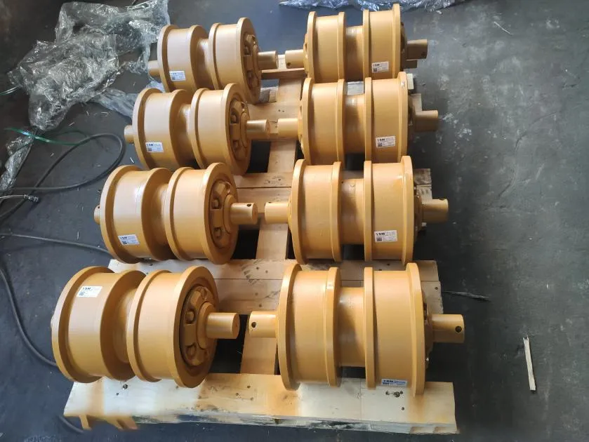
Lower track rollers support machine weight and guide the link rails. Carrier rollers support the upper chain where that configuration uses them. Seal leakage, flange wear, impact damage or a roller that does not rotate freely can change the load carried by neighboring components.
Inspection clues
Look for oil around seals, flat spots, cracked flanges, metal transfer, contact between link and flange, unusual tilt and packed material that prevents rotation. Compare the wear pattern of front, center and rear rollers rather than assuming they all wear at the same rate.
A shiny band on one side of several flanges may point to side loading, track-frame alignment, idler guidance, repeated slope work or turning behavior. It does not prove one cause by itself. Inspect the chain, idler and frame contact pattern before replacing a single roller.
Track roller guards can reduce certain impact exposures but may also retain packed material in some conditions. If guards are fitted, include the hidden areas in scheduled cleaning and inspection. Confirm the actual guard arrangement instead of relying on a brochure illustration.
Front Idler, Recoil System and Track Adjustment
The front idler guides the chain and moves with the recoil and adjustment system. Inspect its tread and flanges for uneven wear, chipping, leakage, abnormal side contact and restricted movement in the track frame. Also look for impact marks and material trapped around the yoke or guides.
An idler that appears too far forward or rearward can reflect chain wear, adjustment position or other system conditions. Position alone does not prove that the idler is defective. Record the observation and compare it with chain measurements and the manual.
The recoil assembly can store dangerous energy. Do not loosen, heat, cut, open or dismantle the mechanism during a routine inspection. Track adjustment must follow the machine-specific procedure, including the approved measuring condition and safe grease-release method.
Sprocket and Final-Drive Area
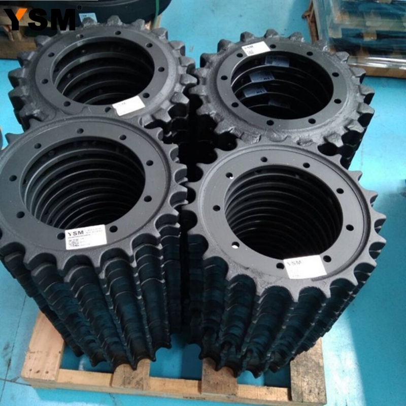
The sprocket transfers drive force into the chain bushings. Inspect tooth shape, root wear, side polishing, cracks, loose hardware where applicable and packed debris. Hooked or sharpened tooth profiles can indicate advanced wear, but the decision must consider chain pitch and bushing condition.
Installing a new chain against a severely worn sprocket, or new sprocket components against a highly worn chain, can produce poor engagement and accelerated wear. Plan them as a mating system. Part identity and allowable reuse should be checked against the exact machine documentation.
Oil near the drive area may come from more than one source. Clean the area and identify where fresh oil first appears. Final-drive diagnosis, oil-level checks and disassembly require the correct procedure; an oily sprocket does not automatically mean the sprocket itself has failed.
Track Shoes, Guards and Jobsite Conditions
Track shoes provide ground contact and transmit load into the chains. Inspect plates, grousers, bolt holes and seating areas for cracks, bending, excessive wear and movement. A damaged shoe near a bolt hole deserves a careful check of the hardware and both link pads.
Wider shoes can improve flotation on soft ground, but they also place more material outside the link support. On firm, rocky or uneven surfaces, that extra width can increase bending leverage and side stress. The correct choice balances flotation, stability, impact and the approved configurations for the machine.
Triple-grouser shoes are associated with crawler excavator travel and turning, but exact width and design still vary. Do not order from width alone. Record the hole pattern, center spacing, grouser style, plate profile and chain information requested by the supplier.
Track Tension and Operating Habits
Track tension changes the way components load one another. Excessive tension can increase loads through pins, bushings, idlers and rollers. Excessive looseness can allow poor guidance, impact or derailment risk. Packed material can temporarily tighten a track and distort an otherwise valid measurement.
There is no safe universal sag value for every PC210LC-11 configuration and condition. Use the current operation and maintenance manual for the exact machine, prepare the track as directed, park it in the specified condition and measure between the stated reference points. Do not copy a number from a different model or an online discussion.
Habits that help control wear
- limit unnecessary high-speed travel and long reverse travel;
- avoid repeated sharp pivot turns when a wider turn is practical;
- alternate travel direction and machine orientation where the job allows;
- reduce track spin and side loading on rocks or demolition debris;
- keep harmful packed material from building around the track frame;
- record major changes in soil, slope, travel distance and attachment use.
Operating technique cannot eliminate normal wear, but it can reduce avoidable impact and help both sides wear more predictably.
Measurement and Repair Planning
A complete undercarriage survey is more useful than replacing the first visibly worn part. Clean the reference points, use calibrated tools, follow the correct measurement method and record actual values. Useful observations include link and rail wear, bushing wear, roller and idler tread wear, sprocket profile, shoe condition and adjustment position.
| Observed condition | Possible contributors | Next check |
|---|---|---|
| One side wears faster | Slope work, repeated turning, travel direction, packing or geometry | Compare work cycle, roller flanges, idler guidance and chain measurements |
| One roller leaks or has a flat spot | Seal damage, impact, internal wear or seizure | Confirm rotation, temperature pattern and effect on neighboring components |
| Sprocket teeth are hooked | Pitch change and bushing-to-tooth wear | Measure the chain and inspect external bushing wear |
| Shoes move on the links | Loss of clamp, damaged hardware, holes or seating surfaces | Inspect bolts, nuts, holes and both link pads |
| Fresh side polishing | Side loading, guidance or alignment conditions | Map contact across rollers, idler, guards and both track groups |
| Track tension changes quickly | Packing, adjustment leakage or component condition | Clean, repeat the approved measurement and inspect the adjuster area |
The table organizes diagnosis but does not establish a cause. Repair decisions should consider the whole wear system, safety risk, expected working hours, planned job conditions and the applicable limits.
PC210LC-11 Undercarriage Parts Fitment Checklist
For a replacement-parts review, send enough information to distinguish the actual machine and track group:
- equipment brand, complete model and every visible model suffix;
- serial number or product identification number and a clear plate photo;
- part name, required quantity and readable part number where available;
- overall, side, mounting and damaged-area photographs;
- requested dimensions with a clear description of the measuring points;
- shoe width, grouser style, bolt pattern and master-connection details;
- link count or other chain identification when requested;
- left or right position if the component is side-specific;
- destination country and typical ground, travel and impact conditions.
PC210LC-11, PC210LCi-11 and other PC210 series names must not be assumed to share every component. Compatibility and availability require confirmation before ordering.
Frequently Asked Questions
How often should a PC210LC-11 undercarriage be inspected?
Operators should include a visual check in the daily walk-around. Measurement intervals depend on job severity, hours, travel and the maintenance plan. Harsh rock, demolition, heavy packing or rapid wear may justify more frequent documented surveys.
What causes uneven track wear on one side?
Repeated turning in one direction, slope work, travel direction, packed material, side loading and alignment conditions can contribute. Compare operating history and the complete left and right wear patterns before assigning a cause.
Can track tension be checked with a universal sag number?
No. The preparation, machine position, measuring points and acceptable value must come from current documentation for the exact configuration.
Should a track chain and sprocket be replaced together?
They should be evaluated together because their wear surfaces engage. Whether either component can remain in service depends on measurements, profile, limits and the planned repair strategy.
Is the model number enough to order track rollers?
No. Send the complete model, suffix, serial information, part number or casting marks, photos, dimensions, quantity and destination. Production and installed-configuration differences must be checked.
Technical References
- Komatsu: PC210LC-11 and PC210LCi-11 Product Brochure - model identification, undercarriage layout and described equipment options.
- Komatsu: PC210LCi-11 Product Brochure - current product information and maintenance-oriented machine features.
- Komatsu: Do Not Overlook the Undercarriage - cleaning, inspection, track tension, shoe selection and operating practices.
This independent educational guide is not affiliated with or endorsed by Komatsu. Komatsu and the model names are trademarks of their respective owner. Always follow the operation and maintenance manual, service instructions, wear chart and site safety procedures for the exact machine.
Ask About PC210LC-11 Undercarriage Parts
We can check suitable supply options for track rollers, carrier rollers, front idlers, sprockets, track chains, track shoes, track assemblies and related undercarriage hardware after reviewing the exact machine and application.
Corporate Email: sales@china-ysm.com
WhatsApp: +86-18606961587
For a fitment check, send the equipment brand, complete model and suffix, serial number or PIN, part name, part number, clear photos, requested dimensions, quantity, destination country and working conditions. Compatibility and availability must be confirmed before ordering.