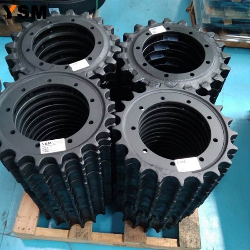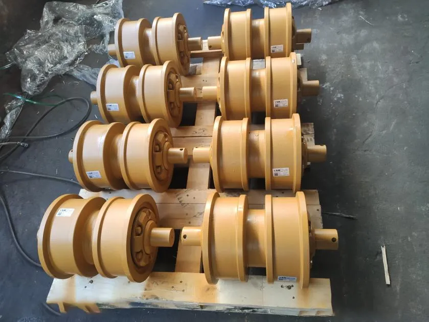

Lower track roller condition and chain guidance
Excavator Track Roller Flange Wear: Causes and Inspection
Excavator track roller flange wear should be checked separately from tread wear. The roller tread supports the link rails, while the flange surfaces help guide the chain laterally. A roller can retain a reasonable tread diameter and still show strong side contact, a damaged flange, or an unsuitable wear pattern. Replacing that roller without investigating the chain path may leave the original problem in place.
1. Identify the tread and flange wear surfaces
The tread is the running surface that contacts the link rails. Flange side faces guide lateral movement, while flange tops can show a different contact pattern if the chain runs outside its intended position or the surrounding wear geometry has changed. Record the exact surface instead of describing everything as "roller wear."
Lower rollers can have different flange arrangements, mounting features, and installed sequences. A broad parts description such as single-flange or double-flange is useful, but the actual profile and position must agree with the serial-specific parts information. Do not change the sequence merely because another machine uses a different arrangement.
Light contact marks may be consistent with service. Deep side grooves, asymmetry, cracking, metal displacement, or a changing contact pattern need closer assessment against the correct dimensions and operating history.
2. Record the pattern before diagnosing the cause
| Observation | What to compare | Next inspection |
|---|---|---|
| One flange side wears more | Opposite flange and corresponding roller on the other crawler | Chain side contact, guidance, mounts, and work direction |
| Several rollers share the same side pattern | Front-to-rear sequence and link side faces | Complete chain path, idler guides, guards, and frame |
| One roller differs from its neighbors | Part marking, profile, mounting, and tread readings | Local mount damage, mismatched part, or roller condition |
| Flange top has impact marks | Link pin bosses, rail wear, and guiding contact | Actual interference and chain movement |
| Flange damage accompanies leakage or a flat tread | Seal condition, temperature history, and rotation evidence | Whole roller assembly and mating rail condition |
These observations are starting points. They do not prove that alignment, tension, or the roller itself is the sole cause.
3. Possible contributors to uneven roller flange wear
Repeated lateral loading
One-direction turning, repeated tight turns, uneven ground, and side-slope duty can concentrate contact on one side. Caterpillar's undercarriage management guide identifies repeated turning in one direction as a contributor to link-side, roller-flange, and idler-flange wear. Review the work pattern before assuming that a new roller will wear evenly.
Shoe selection and working conditions
A wide shoe supplies flotation but increases leverage in some hard or high-impact applications. The same Caterpillar guide warns that unsuitable shoe width can increase interference and wear among links, rollers, and idlers. Match shoe selection to the actual application and machine guidance.
Guidance, mounting, and installed components
Inspect the idler guides, track guards, roller mounting faces, fasteners, and frame for damage or unintended contact. Check whether a replacement roller has the correct flange profile and offset. Similar shell diameter does not establish compatibility.
Chain condition and adjustment
A worn or poorly guided chain can change lateral movement and contact. Packed material also changes the conditions under which adjustment is checked. Measure the track by the applicable manual rather than making it unusually tight to suppress side movement. Tightening cannot repair damaged links, worn guide surfaces, or a distorted mount.
4. A repeatable flange-wear inspection workflow
- Park and isolate. Use stable level ground, lower the attachment, stop the engine, and follow the exact manual.
- Clean the contact area. Expose the flange, tread, links, guards, and mounting faces without damaging seals.
- Label each position. Record crawler side, front-to-rear roller number, and inner or outer surface.
- Photograph square-on. Add an overall view and a scale where safely accessible. Show neighboring components.
- Measure the tread separately. Use the specified caliper, depth-gauge, or ultrasonic method and correct wear reference.
- Document flange condition. Record side loss, cracks, impact marks, and any approved flange dimension independently.
- Inspect the mating chain. Check rail condition, side faces, pin bosses, stiff joints, and pitch using the prescribed span.
- Compare both complete sides. Look for a local fault, repeated system pattern, or a change since the last inspection.
TrackTreads describes multiple roller measurement methods. The chosen method and reference surface must be suitable for the installed roller; a raised lip or uneven tread can make an unqualified reading misleading.
5. Decide the repair scope from condition and cause
A cracked or broken flange, severe interference, loose mounting, active lubricant loss, or repeated track displacement requires qualified assessment before continued production use. An acceptable reading on one surface does not override a separate defect.
Possible actions include monitoring a stable pattern, correcting a mount or guide issue, replacing a damaged roller, or planning several mating components together. The exact manual and service assessment determine the limit. Do not apply a generic allowable missing-flange angle or dimensional threshold from another design.
Roller relocation, shell rebuilding, welding, or grinding are not universal field remedies. Use them only when an approved procedure applies to that roller and machine. After repair, establish a new measurement record and check whether contact has returned to the intended path.
6. Data needed for a replacement track roller
- Machine brand, complete model, serial number or PIN, market, and application.
- Roller side, installed position, flange arrangement, readable part number, and quantity.
- Shell and tread dimensions taken from agreed reference surfaces.
- Mounting-hole centers, overall mounting width, shaft or bracket details, and offsets.
- End, side, mounting-face, and installed-position photographs.
- Wear measurements and photos of the chain rails, pin bosses, guards, and idler guidance.
- Previous repair, shoe width, working conditions, and destination country.
Label every measurement on a drawing or photograph. Confirm the replacement profile and mounting before removal where possible. Correct the source of abnormal side loading as part of the same repair plan.
Frequently Asked Questions
Does flange wear always mean the track frame is bent?
No. Turning pattern, side loading, guidance, chain wear, adjustment, local mounts, and component mismatch can contribute. Verify the cause with inspection and measurements.
Can a roller pass a tread check but still need attention?
Yes. Flange damage, leakage, restricted rotation, cracking, or mounting problems are separate findings that may require action.
Should I tighten the track to stop flange rubbing?
Use only the prescribed adjustment. Excess tension increases component load and does not correct damaged guidance or mounting.
Can a single-flange roller replace a double-flange roller?
Do not assume interchangeability. Confirm the exact part, profile, installed sequence, serial applicability, and mounting dimensions.
Technical references
Check Track Roller Replacement Options
Our China-based manufacturing and wholesale supply team can review the requested undercarriage parts using the machine identity, installed roller details, and inspection findings. Suitable supply options can be checked for:
- track rollers and carrier rollers;
- front idlers, sprockets, and track-guidance-related items;
- track chains, shoes, assemblies, and related fasteners;
Corporate Email: sales@china-ysm.com
WhatsApp: +86-18606961587
Compatibility and availability must be confirmed from the complete model, serial number, part number, clear photos, and requested dimensions before ordering. Include quantity, destination country, and working conditions.